In this tutorial I’ll show you how to control simple 10 LED Bar Graph array w/ Arduino or Arduino clone MCU and MAX7219 (also works with MAX7221) LED controller chip. Here’s video of finished product in action
About LED Bar Graph arrays

LED Bar graphs is basically just several LEDs arranged in a row but in single package. These are very useful as indicators for displaying levels of something (i.e. sound volume). They vary in color and number of LEDs in the array. Some use multicolor LEDs, some single color.
However this tutorial is for a “simple” bar graph which means each LED in the bar has 2 leads (positive a.k.a. anode and negative a.k.a. cathode). So 10 LED Bar Graph will have 20 pins. I used part that had 7 Green and 3 Red LEDs (purchased from Digi-Key p/n: 754-1671-5-ND), but you can easily adapt it to different lengths of arrays.
Parts Needed:
-
10 LED Bar Graph (Digikey)
-
30K (or 33K) 1/4W Resistor (TaydaElectronics)
-
Mini Perfboard (Radioshack)
-
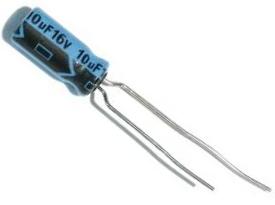
10uF 6V or 25V Polarized capacitor (TaydaElectronics)
-
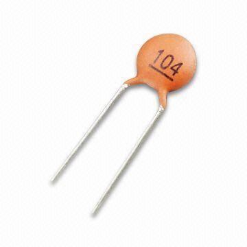
0.1uf (code 104) ceramic disk capacitor (TaydaElectronics)
-
MAX7219 (or MAX7221) LED Display Driver IC (TaydaElectronics)
-
Arduino or clone
-
Breadboard (optional)
Tools and supplies:
-
Hookup wires
-
Solder w/ rosin core
-
Soldering iron
-
Safety glasses
Problem and Solution
(feel free to skip this part and go straight to assembly part)
I was working on a remote volume control device and needed some kind of way to display volume level. For this I chose 10 LED Bar Graph display that I got from Digi-key (p/n: 754-1671-5-ND). It was supposed to be controlled by my arduino-like board(based on ATMega328p chip). In theory you can drive something like this straight from Arduino without special driver IC, however it will use up a lot of pins and LEDs will not be as bright due to ATMega’s power limitation. I wanted to use minimum number of pins (preferably no more than 3) so I’ve carefully considered my options.
One option is to use Shift Register to “multiply” useful micro-controller ports. With just a few pins via Shift Register one can control up to 8 LEDs. With addition of another Shift Register it can be 16 LEDs and so on. One issue besides using two ICs for the task was powering LEDs. Neither ATMEga chip nor Shift Register can provide enough power for the task, so transistors will have to be used. In addition each LED will need to be connected to a resistor to limit it’s current. This increases part count to a pretty big number (2 Shift registers, 10 transistors (or 2 transistor array ICs), and 10 resistors). This is where dedicated LED driver chip comes into play.
Most popular one is MAX72XX chip. It can handle up to 64 LEDs and requires only 3 pins from micro-controller. As a bonus there are lots of tutorials about using it with Arduino. Unfortunately I could not find a single tutorial that will explain how drive LED Bar array that’s not multiplexed (meaning each LED has separate leads). But don’t worry I will explain everything! 🙂
MAX72XX and LED multiplexing
(again feel free to skip this part, if you are not interested in know how everything works)
MAX72xx series (MAX7219 and MAX7221) LCD driver can control up to 8 seven segment LED displays or 64 individual LEDs (great for 8×8 LED matrix). However you can’t just connect 64 LEDs directly as chip only has 24 pins, and only 16 of them are meant to be connected to LED displays. That’s why its important to connect individual LED pins into a matrix.
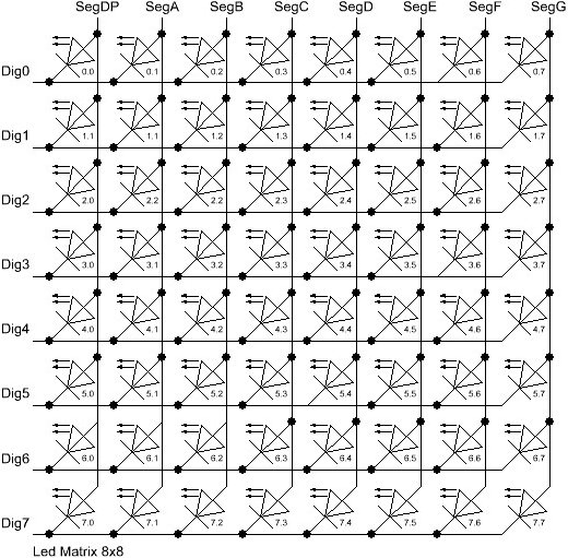
But how would you do it? For this a little understanding of how MAX72xx chip sees LEDs is needed.
This driver IC has 8 “digit” pins (0-7) and 8 “segment” pins (SegA-SegF and SegDP). If you think of digit pins as rows and Segment pins as individual LEDs, you can see how 64 LEDs can be used. Because each row can have up to 8 LEDs all you do is connect cathodes of these 8 LEDs together and then to a digit pin (i.e. DIG0) of MAX72xx chip. Anode of each of 8 LEDs then connected to single Segment lead of the IC. For the first row you using up 9 wires (1 to DIG0 and 8 to SEG).
Then you take next 8 LEDs, connect all of it’s cathodes together to DIG1 and to same 8 Segment pins as 1st row. You now have total of 10 wires connected, but driving 16 LEDs! See how it works? Next 8 LEDs connected just like ones before it, only to the next available DIG pin (i.e. DIG2) and so on. If you have 64 LEDs you just connected them to IC with only 16 wires! If you want to connect even more you will need to add another MAX72xx chip, but that’s beyond the scope of this tutorial. In our case we only have 10 LEDs, so we will be using DIG0, DIG1 and all SEG pins. Total pins used 10!
Connect it together on breadboard
Before we start soldering, let’s see if everything is working on breadboard.
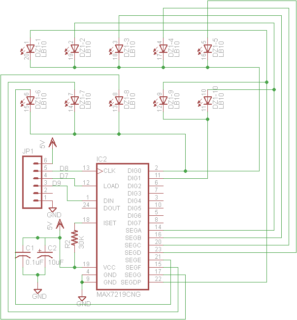
Start by placing MAX72xx chip on the board.
-
Connect GND Pins 4 and 9 to the ground.
-
Connect Pin 19 (VCC) to +5V
-
Place 30K resistor between Pin 18 (ISET) and 19 (VCC)
-
Connect pin 1 (DIN) to Arduino’s D9
-
Connect pin 12 (LOAD) to Arduino’s D7
-
Connect pin 14 (CLK) to Arduino’s D8
Remember you can use pretty much any pins on Arduino, as long as you modify sketch to reflect correct pins.
Resistor is required. It limits current to LEDs. It’s important to use correct value as well. 30K works great for 10 LED Bar, but anything less will make LEDs draw to much current and will shut down IC (i.e. with 10K resistor I was able to light up just 2 LEDs)
Now let’s connect LED Bar to MAX72xx
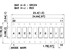
As you can see on this image, you can find PIN 1 by angled corner. From there Pins go up to 10 on one side (These are all Anodes), and the continue on the flip side (Cathodes)
-
Connect together cathode pins of the 1st 8 LEDs (pins 13-20) and connect them to MAx72xx pin 2 (DIG0)
-
Connect remaining 2 cathodes on LED Bar graph (pins 11-12) to MAX72xx pin 11 (DIG1)
-
Connect Anode pins on LED Bar Graph to MAX72xx like in this table:
|
LED Bar Graph Pin |
MAX72xx Pin |
|
1 and 9 |
22 (SEGDP) |
|
2 and 10 |
14 (SEGA) |
|
3 |
16 (SEGB) |
|
4 |
20 (SEGC) |
|
5 |
23 (SEGD) |
|
6 |
21 (SEGE) |
|
7 |
15 (SEGF) |
|
8 |
17 (SEGG) |
Decoupling capacitors
This is optional but recommended. MAX72xx is very sensitive current changes and if you notice some weird behavior you might want to add decoupling capacitors to it’s VCC line.
Connect 0.1uf (code 104) ceramic capacitor between Pin 19 and Ground (i.e. one leg of cap to PIN 19 and second to GND)
Connect 10uf electrolytic capacitor same way as 1st capacitor but make sure polarity is correct (i.e. positive leg (longer lead) goes to Pin 19 and negative (shorter) to the ground).
Both capacitors should placed as close as possible to PIN 19 on MAX72xx chip.
Test it
Double check that everything is connected correctly (especially VCC and Grounds) as MAX72xx is super easy to kill (I managed to fry mine first time I was building this).
Load this sketch into Arduino and see if LEDs start to light up and down just like in the video.
Solder it on perfboard or PCB
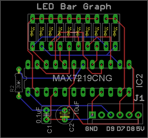
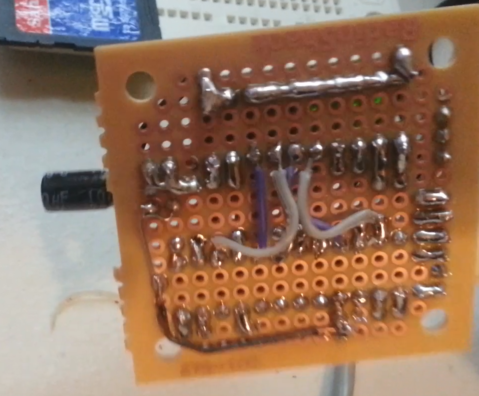
You can either etch your own PCB or just use small perfboard. I assembled mine on small square perfboard from Radioshack.
Just follow schematic, or you can use my board layout. Note: I used polarized connector (J1) on mine. Only 5 pins out of 6 used.
Note: In the video I also have another 3 pin connector. You don’t need it, I used it to connect IR receiver to the same board (for my Remote Volume Controller project)