Almost from very beginning when I started working on Xronos clock I had in mind to implement AutoDimming functionality. Concept is simple and used in smartphones, tablets, etc. In the dark room LEDs become dim, so it don’t bother you when you sleeping. In sunny conditions they become bright so it’s easier to see. Nothing new here 🙂 However it proved to be biggest challenge for me. Only about a week ago I discovered root cause of the issue and found solution.
Brains of my clock is ATMega644p processor, which runs Sanguino bootloader. I’m also using Sanguino hardware files to make it compatible with Arduino IDE. That’s the background information, now to the issue.
Xronos uses 5 out of 8 ATMega644’s available Analog ports. A2-A4 used for buttons, A0 is used for Temperature sensor (I actually use it as digital port because temp sensor is digital), and A1 for photoresistor/light sensor. However no matter what I tried I could not access A1 port! What’s more confusing was I found that addressing A0 port will actually address both A0 and A1! So I could use light sensor or temperature sensor but not both, eve tho the were physically not connected together!
I thought I had a PCB hardware problem, but with help of some great folks at Arduino Forums, I found out that it was software bug in Sanguino port definition file. I’m really surprised that nobody before me noticed this, issue is super obvious, but as to the band aid solution that I applied it was transplanting some lines from other Arduino hardware variants into Sanguino file.
To fix A1 port definition, open pins_arduino.h inside your Arduino\hardware\sanguino\variants\standard folder and change this line:
static const uint8_t A1 = 30;with
static const uint8_t A1 = 15;
There are possibly other ports that affected, but I didn’t have time to go thru all of them.
Since now Light Sensor works, it was just a matter of writing new function and menu option into the code, drilling and hot gluing sensor to the enclosure prototype.
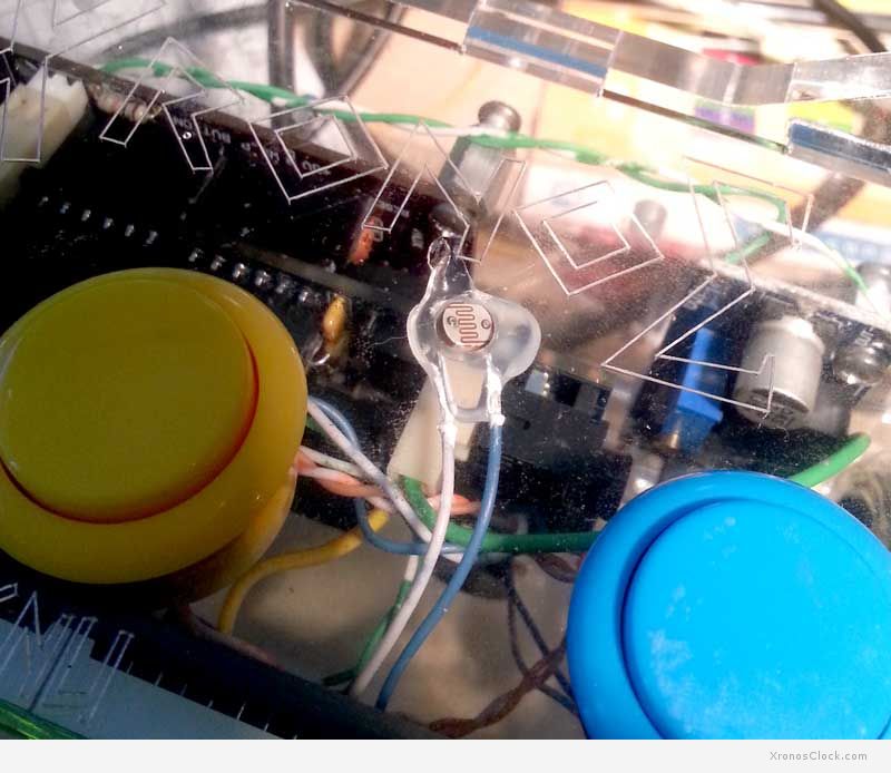
It’s a bigger challenge however to modify current production enclosures to hold this small photo-resistor, and sorry but it won’t happen for a while, at least not until I can sell current stock of 15 clocks…
But you can always add one yourself 🙂 Probably the best way would be to drill a hole in faceplate, and hot-glue sensor from inside to the front panel. PCB already has place for 2 pin connector and 10K resistor so it should be pretty easy. I added functionality to the latest Beta release of the sketch, just change:
#define AUTO_BRIGHTNESS_ON 0
to
#define AUTO_BRIGHTNESS_ON 1
P.S. On the pictures you see enclosure made out of clear acrylic and face plate is mirrored acrylic. This is my first prototype. I think black acrylic looks a lot better, but if I get a lot of requests I can make you custom clear enclosure 🙂