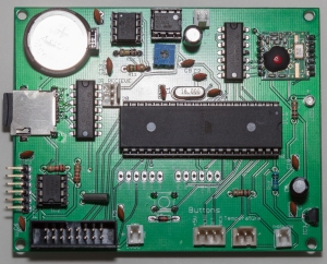
I’ve been working on 2.0 version of PCB for a while, and finally I was able to realize my ideas in hardware. 10 brand new PCBs arrived last weekend, after about 10 days since I placed order on iTead. That’s amazing turnaround time, considering that I chose standard shipping from China.
I’m going to first describe what’s new in 2.0 version and then if you wish you can read whole story of how I build and got it working 🙂 That and there’s “in action” Video, after the break.
New features in Xronos 2.0 PCB:
- Integrated Audio w/ microSD card (based on WaveShield design)
- Wireless radio capability with RF12B module
- Smaller button header (now just 4 connectors instead of 6)
- Both 16×32 and 16×24 (up to 4 displays) Sure LED displays supported! (extra CS pins connected to IDC socket)
- Header for IR receiver (for future functionality)
- 3.3V regulator (to power microSD and RF12B)
- Best part is: microSD card, FTDI header and battery located on the same side (behind maintenance door) so it’s very easy for end user upload firmware, replace battery and remove microSD card to update audio all without disassembling clock!
These new boards are huge comparing to the V1, almost 10x10cm. I wanted to space some sensitive components such as Audio DAC/AMP and RF radio (in the past I had lots of interference when I tried building my audio amp).
I took it slow, soldering parts and testing each component before moving on. Mainly because I’m short on parts and this is literally 1st version of new prototype so I had no idea if it worked. Biggest worry was integrated audio, based on Adafruit’s WaveShield. MicroSD socket was a little difficult to solder due to tiny distance between leads. I had to fix a bridge I created with solder… But to my surprise it worked! Both clock part and audio was working great with ATMega644p chip!
Encouraged I soldered RF12B receiver component. It didn’t work at first. I used RF12B library created by Felix (lowpowerlab.com). It’s a great library but no matter what I tried I couldn’t get receiver to work (sketch would freeze). Remember how buggy Sanguino firmware was, I tried different chip: ATMega1284p with Optiboot. And imagine my joy when RF12B started to work just fine. I did have to make some small adjustments to the pin-out in the library file.
It was time to put everything together (clock sketch and RF12B part) and that’s when I discovered that SD card reader stopped working… I spent 3 days trying to find problem. It worked fine with Sanguino, but not with Mighty 1284p (which BTW worked in V1 PCB). Finally thanks to some helpful suggestions from Arduino forums, I found that issue was with CS (Chip Select) part. I kind of suspected it from the start. SD Card reader had pullup resistor on CS line, but RF didn’t have one.
Anyway as someone pointed out, CS pin of SPI device (both SD Card and RF12B share same SPI bus) needs to be LOW when in use, and all other SPI devices need to have CS pin set to HIGH. As soon as I tried it in the sketch, SD card (and audio) started to work! I still went ahead and soldered 10K pullup resistor on RF12B’s CS pin and VCC. After that, I didn’t have to manually set pin to HIGH. Not exactly sure why…But now i had both SD and RF12B working!
So what is RF12B for you might ask? Well it’s primary role is to receive temperature reading from remote sensor. Remote sensor I used was tiny Moteino which also has RF12B onboard. I can’t stop raving about Moteino because it’s great to work with, not to mention how inexpensive it is. It’s very small, uses tiny amount of power so it’s perfect for battery powered remote sensor. Felix did really great job with it!
Initially I had some conflicts between RF12B and SD card, mainly because RF uses hardware interrupt and will activate itself when it receives pocket of data. When this happens, SD Card stops working and whole thing would just hang. Problem was so bad that I almost gave up, until Felix (dude you rule!) suggested I use radio.Sleep() and radio.Wakeup() functions built into RF12B library. That totally resolved conflict. I would just deactivate radio when playing sounds, and reactive it when it’s safe.
For the test I connected remote Moteino to DS18B20 temperature sensor (with 4.7K resistor between sensor’s data and VCC) powered it by 9V battery and programmed to send temperature (in Celsius) every 30 seconds. I placed in the basement which 3 floors above receiver. Setup worked pretty well. I added voice announcement of the outside temperature as well as info display. Some error handling was also added in case no remote temperature data is received (which normally happens just after clock was reset).
Next step is to get IR remote working with clock. I will probably use it for my wall clock version. Speaking of plans, there’s much more work to be done before Xronos 2.0 will be complete. For one current enclosure is not fully compatible, so I will need to make modifications to back panel. And I doubt I will be selling V2.0 until I sell my current stock of Xronos Clocks V1 (about 10) in order to fund next version production.
Finally here’s video of new prototype in action:


Leave A Comment